STM32G431 Analogue TV Transmitter
Filed under: Software, Embedded, Video
If you follow me on mastodon you might know that I have a bit of an obsession with vintage analogue video cameras. They’re great. I love them. I can’t stop being weird about them. So a few weeks ago I felt like it was finally time to take the next step and get myself one of those “televisions” I had heard so much about. Stop feeding those pristine analogue signals into a digital capture card and instead enjoy them fully analogue, end to end, crt to crt.
So after looking around for a bit, realizing that CRT TVs have gotten stupidly expensive, and finally picking up this adorable thing for 50€ I found myself with a whole new technological rabbit hole to dive into!
Turns out that one of the reasons this TV was so cheap was because it doesn’t have any video input besides an antenna. And it’s black and white. Both of which are deeply disappointing to gamers. And since analogue video broadcasts around here have stopped like a decade ago I couldn’t even enjoy our high quality domestic TV programming, let alone connect any of my weird cameras.
So, there’s two options here, basically: Either, mod the TV for composite video input (not too hard) or just get an RF modulator (easy).
We have RF modulator at home

Unfortunately this is the only photo I have of the actual setup… 
Looks kinda awful, in a good way 
The latest in RF amplifier technology


Ok, but what if I just built my own RF modulator (much harder!)?
Luckily I’m in the possession of this beautiful Phillips PM5145 wide band generator which, while it only goes up to 12MHz, hasn’t been serviced in so long it outputs enough harmonics to get a signal up all the way to 48.25MHz, the frequency of channel 2 around here. (We don’t talk about channel 1…) And luckily it even has an AM modulation input!
After realizing that broadcast television uses negative modulation I was able to hack together a little inverter and amplifier circuit, hook up one of my cameras and get beautifully bad looking low latency video, no computers involved! Easy!
Let’s involve some computers
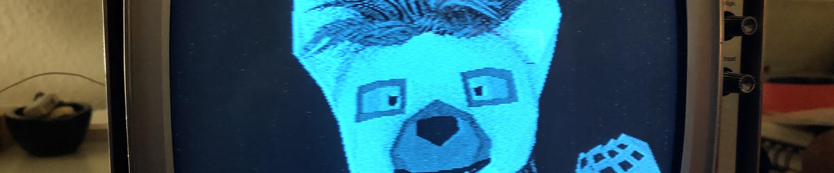
Ok, this is nice and all, but… can I make the TV display an image of my fursona1? And more importantly, can I do it without having to mess around with a bunch of RF stuff on a breadboard?
I dug through my pile of small dev boards and found a NUCLEO-G431KB, a small development board for the STM32G431, a microcontroller which, according to ST, features “Medium Analog level integration”. That’s just the amount of analog(ue) integration I was looking for!
The main thing I though that might make this possible is the fact that the internal operational amplifiers on this chip support input muxing, allowing them to quickly switch between different input signals. If I could make them switch fast enough, well… that’s basically an RF modulator right there.
Undeterred by the stated bandwidth of only 10MHz I set up a quick test: With the CPU frequency set to 96MHz and the muxer set up to toggle every clock cycle, could I get a 48MHz carrier my TV could receive by just connecting one of the opamp inputs to ground and the other to 3.3V?
Yes! A perfectly silent black screen! The output signal is tiny, but it’s enough to receive on my TV if I connect a wire and wrap it around the antenna!
Let’s make it do video!

Look Ma, I'm on TV! 
I realize the irony of showing off resolution with a very pixelated image…


Ok, next step, can I modulate the RF carrier using a video signal?
The STM32G431 has multiple DACs which advertise a sample rate of up to 1MHz. That’s… not really enough for video. Damn. But taking a closer look at the reference manual shows that the same DACs, when not using the internal buffers support a sample rate of up to 15MHz. What? Why would the use of the buffer change the supported sample rate?
Well, it doesn’t. I assume they’re making statements about the frequency response of the buffer here, but stating that in terms of sample rate is… confusing. And it’s not like it’s gonna stop me anyways at this point. I’m gonna make the thing do video if it wants to or not.
So, here was my idea: use the two channels of the DAC to output the envelope of the desired RF signal and switch between the two using the input muxer on the opamp. If the two DACs output the same voltage there will be no signal, and the further I move them apart the stronger the RF signal gets. Unfortunately there is no way to directly connect the output of the DACs to the inputs of the opamp on this model of the chip, so I had to make due with two wires to loop the signal back into the chip. This also meant involving the output buffers which limits the frequency response somewhat, but it still looks pretty good.
To minimize the amount of modulation signal leaking through to the output I decided to keep the two DAC signals centered around the middle of their range, with one of them moving up and the other moving down to increase the amplitude. This doesn’t work perfectly since the analogue switches on the input of the opamp aren’t 100% symmetric at these high frequencies, but it’s good enough.
All I had to do now was to generate a composite video signal and output it through the two DACs in the right way to achieve the desired modulation of the RF carrier.
After a bunch of fucking around with timers and DMA and ditching the horrible ST HAL to make it all go fast enough I was able to output beautiful 8 bit grayscale video over RF at 400x300 pixels!
How’s that for a new years resolution!
What makes me the happiest about this is just how… elegant it is. No relying on harmonics, no bitbanging, no cycle counting, no external components. All the video output generation happens in hardware with minimal CPU involvement. All I need to is memcpy new video data into the DAC buffer. And considering how hacky the whole setup is the resulting video signal is incredibly clean.
At this point I almost felt like I could wrap the project up right there…
Can we make it do audio?
Video is cool and all, but what about audio? And I don’t mean adding a line out to the thing, I mean adding an actual RF audio carrier to the signal.
This should be easy, right? It’s just audio! That’s so much easier than video!
Audio was hard. Really hard. Way harder than I thought it would be. And the main reason for that is that the audio in a TV signal uses FM modulation. And creating a finely frequency modulated signal on a microcontroller is surprisingly hard. And I really didn’t want to have to resort to creating the signal in software.
For reference, the audio carrier in a broadcast TV signal around here is offset by 5.5MHz from the video signal and has a swing of +/- 75kHz. That meant that to achieve somewhat decent audio quality I would have to be able to control the frequency of the signal in increments of preferably less than 10kHz to get around 4 bits of audio resolution.
Setting up a timer to do this is basically impossible. In this frequency range the smallest frequency step you can get out of a timer is around 500kHz. Not nearly fine enough! Even enabling dithering on the timer only increases that resolution by 16 times. At the cost of introducing a lot of noise.
So, timers are out. What other options do we have?
Turns out, the STM32G431 has a secondary internal 48MHz RC oscillator meant to be used with the USB periphery, and it has a feature that might just save the day. USB requires a relatively tight tolerance on the clocks driving communication on the host and device. To allow operation without an external crystal the RC oscillator has the capability to slightly change it’s frequency to match that of the host. This is usually done by the hardware by syncing up to the start of the USB frames, but luckily the frequency trim registers are user writeable when the automatic synchronization is disabled.
Unfortunately a 48MHz clock doesn’t really do us any good by itself. Especially because it can’t be connected to anything but the USB periphery. But luckily the engineers at ST have decided to make it possible to output this clock through the chip’s clock output pin. This allows us to loop the signal back inside and use it as external clock for one of the timers, where we can divide it by 9 to bring it from 48MHz down to 5.33Mhz, which is close enough to be brought up to 5.5MHz using the frequency trim register. This frequency division also further increases the resolution of the tuning by 9 times, vastly improving the audio quality.
The timer itself is set up to output two out of phase signals which can be mixed at a relatively low level with the video signals from the DACs before being fed into the opamp for modulation. This does technically require external components (4 resistors to do the mixing), but they’re passives, so that hardly counts.
Easy, right? No, actually. Because breadboards suck.
Turns out that bringing a 3.3V 48MHz signal out onto a breadboard when you’re also trying to create a 50mV or so RF video signal at that frequency basically completely destroys the tiny RF signal. There might be audio now, but in creating it we’ve also completely obliterated the video signal.
Fixing the mess
Ok, sure, I could just not do this on a breadboard, but what if I did anyways?
Well, we could just switch to a different channel.
Channel 3 is at 55.25Mhz, safely away from all the noise caused by the 48MHz signal. I was hesitant to push the opamp even further out of it’s specified frequency range but it turns out it works just fine! I actually ended up switching to a CPU frequency of 166MHz and dividing the clock by 3 for the modulator. This puts us at 55.33Mhz while giving us some more CPU time to do other things, with the only downside being that the modulation is now slightly asymmetric since it will always spend 1 clock cycle on one of the opamp inputs and two on the other. But fortunately that doesn’t seem to make too much of a difference for the modulated signal. If anything it actually had fewer harmonics than before, which is nice.
It’s not all perfect though. If we want to have the audio carrier at exactly 5.5MHz our pre-division audio carrier needs to be a 49.5MHz. This will still leak all over the breadboard, and actually create another modulation product between it and the 55.33MHz signal at 5.83MHz, uncomfortably close to the audio carrier. And because of it’s 9 times wider modulation it tends to overwhelm our actual audio carrier and distort the sound.
The solution to this is to just ever so slightly detune the audio carrier down to move the undivided carrier further away. It’s not super elegant but it works, at least on my TV.
Or, you know, I could just design a PCB.
Designing a PCB

The VIDEOTHING! 
Yes, it says that on the back too.


Ok, I designed a PCB. Here it is. They haven’t arrived yet but they should be pretty cool. In addition to all the previous features I also added some headers for digital and analog inputs and outputs for composite video and line level audio.
I feel like I got incredibly lucky here because not only was I able to use every pin on the small 32 pin package but I was even able to keep all the digital stuff tucked safely away from the analogue portion doing the external signal mixing. You could even do it all on one layer! All the video generation still happens inside the chip, the external components are just support for making the chip run and getting the signals in and out.
Showcase

Conway's Game of Life, now on TV! 
Small tile engine using Grayscale Dungeon Tileset by genewheel 
Look at how high res I am! 
Text! 
Cool wavy lines!


So what can it do? A lot! I’ve implemented a small tile renderer, a version of conway’s game of life, a text renderer and various other fun effects. For audio I’ve implemented my own version of LPC-10, the audio codec used in the speak and spell, to play back voice snippets. With some external inputs it could easily be turned into a small game console thing, a demo platform, video synthesizer, or whatever other audiovisual thing you want.
For my friends across the ocean I have also implemented support for NTSC video timings, if that’s your thing.
The source code for the library/framework can be found here: https://git.sr.ht/~slyka/tinyvision
It comes with instruction on how to set it up on a breadboard and a bunch of different examples to get you started. If you want to play around with the audio codec it can be found here.
Once the boards are confirmed to work I’ll put their sources up on sourcehut too.
Kris ^-^~
Footnotes
Turns out the bottom layer of Maslow’s hierarchy of needs is actually to display your fursona on as many things as possible. They just forgot about that one.